Design a Trace Table
Add/Edit a Trace Table
To create a Trace Table, click Add in the trace table view. For an existing trace table, select the table and click Edit in the detail view.

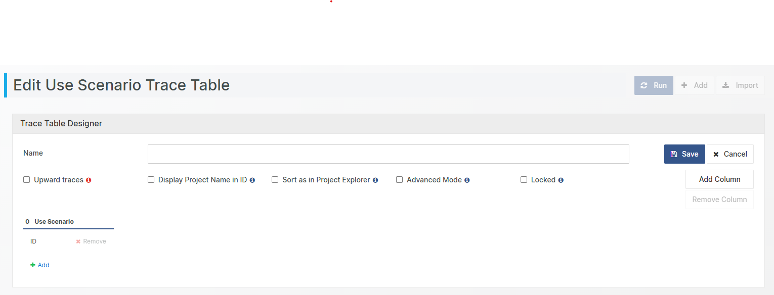
The Trace Table Designer is displayed.
Use the buttons Add Column and Remove Column to add and remove columns. Columns are added and removed from the right.
Each column is of a designated Document Object Type. Furthermore, use the plus and minus buttons to add the attributes to be displayed for the Document Object Type. In the output view, each attribute is displayed in a separate column.
To run the Trace Table, you need to save it first. If the Trace Table has not been saved before, you will be prompted to add a (unique) name for the trace table. Click on the Save button then click Run. This will populate the output view with the column definitions. The sort order is based on the IDs in the left most column (the input set).
Trace Table Input Sets
The input set specifies the Document Objects that make up the “root” of the Trace Table. These objects are used to populate the trace table’s left most column in ascending ID order. There are three different Trace table input set types:
From Database – all most current document objects of the selected type in the main project
Query – the Document Objects that are resulting from the selected query.
Customized – a hand-picked set of Document Object among the most current document objects of the selected type in the main project.
Form Snapshot – the left most column is populated with document of the given type from the snapshot and the rest of the trace table is populated with document objects from the time of the snapshot. Note that the columns to the right of the left-most column do not exclusively contain document objects from the snapshot! They contain the traced items, traced at the time of the snapshot.
Upward Trace Tables
When editing a trace table, tick the checkbox Upward traces to define a Trace Table showing traces in the upward direction. Remember that Aligned Elements traces are uni-directional, pointing from a source Document Object to a target Document Object; using the upward trace table enables depiction in the reverse direction.
Note! Running an upward trace table is considerably more resource intense than a downward trace table. Therefore note that this performance intensive operation may take some time before it completes.
Display Project Name in ID
Ticking this checkbox will include the Project Name of the Document Object in any ID column. This is particularly usefully when populating the Trace Table with document objects from several projects.
Sort as in Project Explorer
This checkbox only affects the document object type of the left-most (first) column. Ticking this checkbox will sort these document objects as they are sorted in the Chapter View. Not ticking this checkbox will sort the document objects in ID number order.
Trace Tables in Advanced Mode
Tick the checkbox Advanced Mode to activate a multi-branch Trace Table.
When activating this mode, all columns to the right of the second column receive an additional number selection field for specifying the parent column. In the example above, the third column (the Use Case column) specifies the first column (the Requirement column) as the parent column.
In the output view, the second column shows specification tracing from the requirements in the first column, and the third column shows use cases tracing from requirements in the first column.
This can be particularly useful when compiling trace tables for Risk Items such as for Failuremodes or PHA which involves several Document Object Types.
Note! All Risk Factors (Severity, Probability, etc.) and Risk Reduction Factors (Probability Reduction, Severity Reduction, etc.) must be present in the table in order for RPN, NRPN, Thresholds, etc. to be correctly calculated.
Furthermore, the Advanced Mode also permits the use of Queries to populate the columns in order to restrict the search set of the Trace Table.
Lock a Trace Table
Users with Project Management user rights have the possibility to Lock (and unlock) a Trace Table design by checking the Locked checkbox. A locked Trace Table design cannot be edited or deleted by other users.
How to delete a Trace Table
Use the button Delete in the detail view to delete the Trace Table.
